Infra-Red Remote Control Systems.
Just about every piece of domestic hi-fi or video unit comes with a remote control handset these days. Despite being so commonplace, when trying to find out how to emulate one for a project Im working on, I found surprisingly little information on how they actually operate. Obviously, they flash one or more LEDs in some kind of meaningful sequence but how they prevent interaction between different units and are oblivious to bright room lights was something of a mystery until I worked out their secrets.
The Dark Ages.
First, a brief history lesson, taking us back all of 25 years. Before then the only remote controls were wired, they extended the front panel knobs and switches of the equipment to a duplicate set at the far end of the cable. These worked well but left a fairly hefty multi-core cable trailing across the room which was unsightly, and possibly dangerous as it had to carry mains power to the remote on/off switch. The first wireless remote units were quite primitive and only had one function, to change TV channel. These only had one command which was to move to the next higher channel number. It wasnt a problem back then because there were only three channels so it didnt take long to go full circle back to a lower number. They used an ultrasonic principle, the receiver was a microphone feeding a narrow band filter and the presence of a tone initiated the channel jump. The transmitter end, inside the handset was, quite incredibly, a tuning fork! A spring-loaded hammer hit the metal fork when the button was pressed and a tone was produced. The frequency was quite low, usually about 20Khz, just above hearing range. The problems with this system were two fold; only one command was available and anything else making a similar noise would activate the receiver. One of my favourite tricks when working in the TV trade back then was to simultaneously change channel on all the TVs in the showroom by shaking my bunch of keys!
The Light Ages.
The first infra-red controls appeared about 20 years ago, its worth remembering that quality LEDs were not commercially available until the late 1970s and even then it took a while for bright ones to be developed. Infra-red opened a whole realm of possibilities because for the first time it was feasible to send coded commands and control more than one function. In the UK, Plessey and Philips were quick off the mark at making transmitter and receiver chip pairs. Unfortunately, and rather short sightedly, their first attempts assumed that only one receiver would be in range of a handset so they made no attempt to add coding to distinguish one receiver from another. I remember well how a close friend used to tear his hair out when he bought a very early DNT satellite receiver and found it responded to his TV remote control as well as its own. No matter how hard he tried, he couldnt keep the TV on channel 6 to watch the satellite receivers UHF signal while trying to watch Sky TV. The simple task of changing satellite program involved placing his hands in various places on the TV to obscure the light beam while waving the remote around with his other hand! What made it all the more infuriating was that neither the TV or satellite box had manual controls yet he had to go right up to them to use the remote!
Ive digressed from technical matters. The fix to stop the wrong receiver responding was simply to add a special sequence of flashes, called the address field, to the flashes conveying the command. Any receiver picks up the flashes but only the one recognising its particular address code would respond. This principle is still used right up to the present day. The problem of activating the wrong unit hasnt been completely eliminated, as there doesnt seem to be anyone controlling which addresses get allocated, at least for all but the RC5 and RC6 systems, which are licensed and controlled by Philips. However, the problem has diminished to a very few cases these days.
Filtering.
Before going in to the details of how the address and commands are represented by light flashes, lets take a look at the steps taken to make receivers immune to ambient light. If you think of the relatively low light output of a remote control handset and the need for it to be seen with bright sunlight shining directly at the receiver, you get some idea of why some sort of filtering is essential. There are three protection systems to allow the wanted light to be seen through the ambient light noise. The first is a physical barrier to all but infra-red wavelengths. Usually, this is a plastic window on the outside of the equipment, dark coloured in visible light but transparent at the longer wavelengths of IR. Combined with a similar plastic window in the actual detector device, most of the spectrum is blocked from ever reaching the detector element. The second level of protection comes from an AGC circuit. This tracks the average light level, letting only instantaneous increases, such as the extra light flashes from the transmitter through. This has to be done because there are other sources of infra-red light around and the receiver must adapt to regard them as normal. The final stage of protection is to use a carrier rather than continuous light pulse. Instead of simply turning on and off in the pattern of the bytes being sent, the zeroes are sent as no light, the LED is off, and ones are sent as rapid pulses. It is rather like 100% amplitude modulation on a carrier at around 40KHz, figure 1 explains all.
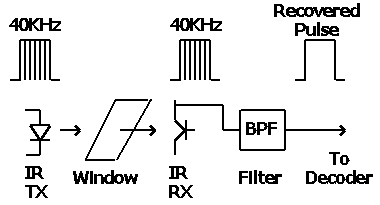
The exact frequency varies from one manufacturer to another but generally lies within the range 35 to 45KHz. By using a carrier it is possible to electronically filter the signal from the detector, further lessening the chance of random pick-up being recognised. In recent times a new problem with filtering has arisen; that of low-energy compact fluorescent lamps. These lamps are becoming more and more popular but the light from them is actually rapidly pulsed, usually at around 50KHz and at such high brightness this can still produce signals than can squeeze through an electronic filter. The process of decoding the data should eliminate misinterpreted signals though.
Sending the bits.
There are three types of modulation and of each of these, a multitude of protocols.
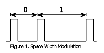
I will explain the common protocols later but for now, lets look at how the binary bits of the command are actually converted to meaningful light flashes. The first common system is called space width modulation and is shown in figure 2. In this system, the on periods are constant and the gap off periods are either short (typically 400uS) or long (typically 1200uS). A pulse followed by a short gap is deemed to be a one and a pulse followed by a long gap is a zero. The on period itself is usually about 300uS long. Because the final gap is impossible to measure, an additional on must be added to mark its end. This type of transmission is economical on battery life because only brief bursts of current are needed, as all on periods are short.
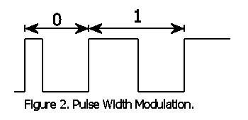
Very similar to space width modulation is pulse width modulation, see figure 2.
The same principle applies but this time the gaps are of constant length and the duration of the on period is changed. It is slightly less economical on battery power to do this but it offers slightly better rejection of repetitive interference such as that from electronic lamps.
The third common system is phase modulation, see figure 3.
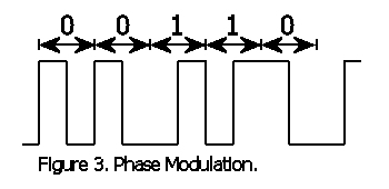
Timing is everything in this method as ones and zeroes contain both on and off periods. A one is represented as an on followed by an off. A zero is represented by an off followed by an on. In other words, the on and off are reversed between one and zero bits. This is a little more complicated than using straight forward timing differences but it has the advantage of better error rejection. Certain combinations of bits are not possible so if they are seen it implies the command should be rejected.
Receiving the bits
Command decoding chips are quite rare these days. The ability to recognise patterns and measure timing intervals with a microprocessor has made them almost redundant. In modern receivers, the one or zero from the filter is fed directly to a pin on the processor and the assembly back into bytes is done in software.
Both of the width modulation methods can be decoded in the same way. The processor waits for the start of a pulse, times the interval to the start of the next pulse and decides whether it lies between acceptable duration to be a one or zero. If it doesnt fit the expected times, the command is rejected and has to be resent
Phase modulation can be decoded in one of two methods. The most obvious way is to rely on the known duration of one bit period. Usually, this is 1.778mS so if the sampling rate is twice that speed it is possible to detect the first and second halves of the bit separately. From this it is easy to decide whether the on or off came first and hence what the bit was. A second method is conceptually a little more complicated but easier to work with in software. It relies on the fact that the time between rising edges is always one, two or three bit lengths. One bit length implies no change in the bit polarity, two bit lengths means it must be inverted three implies a change and back again. As phase modulation protocols always start with a one, the byte can be reconstructed by selectively inverting the following bits until all have been received.
The Protocol.
By protocol, I mean the way in which the combination and timing of flashes is made to convey information to the receiver. This is where each manufacturer takes their own route. In order to do something useful with the recovered bits it is necessary to treat them as a long word of ones and zeroes. Within the word is the address field and the command field. According to the manufacturers specification, the word is split into these two fields and the address is compared with one hard coded into the unit. When a match occurs, the unit knows it is seeing data intended for it and it then decodes the command field to see what action has been requested. The number of bits in each field is up to the manufacturer but is typically 5 bits for the address and 8 bits for the command.
Most of the width modulation systems use an additional protection method; the data is sent twice, first in normal polarity then with the bits inverted. Note that this isnt the same as inverting the signal to the LED, it means that the pattern of gaps and pulses is reversed. The units software inverts the second half and compares it to the first half. If they match, the command is deemed to be valid, if they dont, it is rejected.
Phase modulation usually follows the Philips RC5 or RC6 protocols. In RC5, the first bit is always a one. The second bit is normally a zero but can be a one to signify an extended command is being sent. The third bit is called the toggle bit and it has a special meaning. If a new key on the remote control is pressed, it is set to a one, if the same key is pressed again, or the key is held down so it automatically repeats, the bit is set to zero. The following five bits are the address field and the next six bits are the command. RC5 is not inverted and repeated like the other protocols. RC6 is very similar to RC5 but uses extended lengths in the fields.
The two protocol types are shown in figure 5.
| 1 |
0 |
0 |
0 |
1 |
1 |
1 |
0 |
0 |
0 |
0 |
1 |
1 |
0 |
1 |
0 |
... |
| A |
A |
A |
A |
A |
A |
A |
A |
D |
D |
D |
D |
D |
D |
D |
D |
... |
| 1 |
X |
0 |
0 |
0 |
1 |
1 |
0 |
0 |
1 |
1 |
0 |
0 |
1 |
| 1 |
E |
T |
A |
A |
A |
A |
A |
D |
D |
D |
D |
D |
D |
Home experiments.
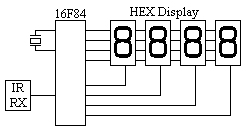
My interest in remote control comes about because I have a project that involves a need to control a VCR. I could wire directly to the electronics of the VCR but I decided to use a non-invasive approach instead. All the functions of the unit I need to use could be controlled from the hand-held remote unit so I decided to emulate it in software and aim an LED at the VCR instead. After a few attempts I managed to decode the pulses from the original remote and display the address and commands on a hexadecimal display.
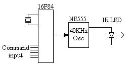
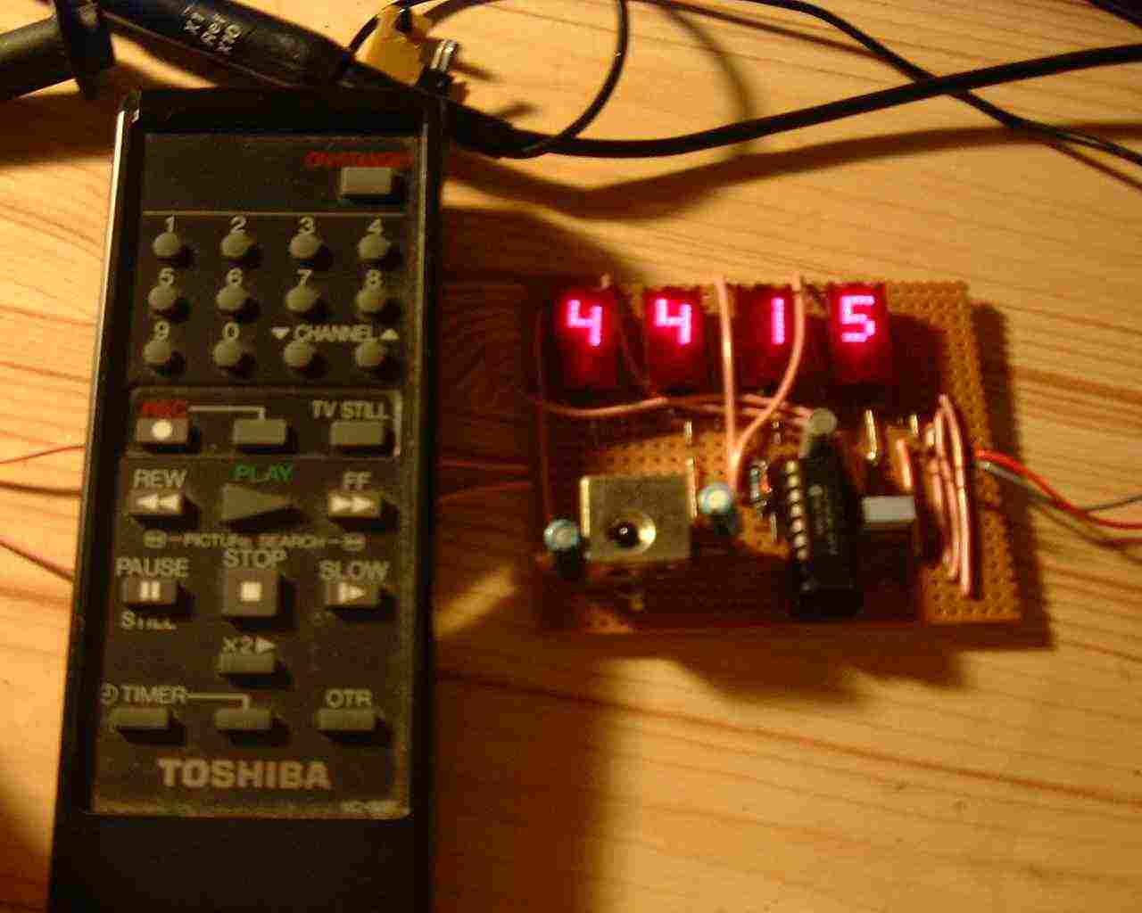
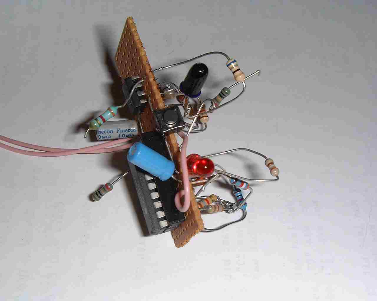
The decoder block diagram is in figure 6 and the photographs shows the constructed board. The encoder was made next, my design will be driven from computer data bus but for testing purposes the command field input was hard-wired. I decided not to try to create the carrier in software because it made the timing rather difficult so I used an NE555 instead. This chip can also source enough current to operate the LED directly.
Here the address is 10001110 and the command is 00011010 and the whole sequence is repeated with ones turned to zero and vice versa.
In RC5 the first bit is always 1. the second bit is usually 0, the T is only a 1 if a new key is pressed. The address here is 00110 and the command data is 011001
I'm only neat when I have to be !