LED Emergency Lighting
OK, so this isnt exactly related to ATV but it might be of use to someone in a similar situation to mine. I live in a very rural area, well away from city lights (thank goodness) and at nighttime it gets very dark. So dark that unless there is moonlight it is hard to move around outdoors and without artificial lighting, impossible to do anything at all indoors. Normally, we are spared the inconvenience of groping around by switching the lights on of course but one of the drawbacks of being remote from civilisation is the unreliable mains electricity supply. Fortunately, my home was bought in dire need of restoration and all the existing electrical wiring had to be replaced, this gave the opportunity to add additional wiring for an emergency lighting supply at the same time.
The backup lighting was never intended to be used as a main source of illumination but as a way of allowing us to safely move around in the absence of the main lights. It didnt take long before the benefit of the extra work was seen, before we had even finished the restoration work we had a 24 hour long blackout and a few months later we were without electricity for three days. The emergency lights were invaluable and worked better than envisaged, to the point that we could just about prepare food, eat and read under them. Not at all bad when you consider they are all LEDs!
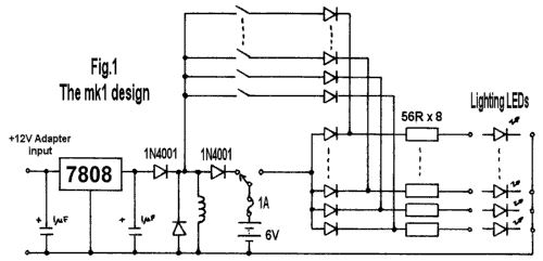
Initially, the mark 1 light controller was used and it was very successful. When tested by deliberately switching its charger feed off, the lights were still usable after running all day and night for a week. The recovery time when the charger was switched on again was about 8 hours. The schematic for the mark 1 version is shown in figure 1. It is basically a regulated battery charger to keep the battery topped up while the mains is present and a mains supply operated relay. When the mains fails, the relay de-energises and switches the LEDs on. Some additional circuitry is provided so that the automatic switching can be overridden as we found it convenient to keep one of the LEDs on all the time as a night-light in our hallway.
The mark 2 version was developed to overcome some of the deficiencies of the original design. Most notable of these is the lack of any way to turn the emergency lights off when they are not needed, like during the daytime! While redesigning to controller, I decided to allow more LEDs to be used to give better illumination in some areas of the house.
The Mk1 limited the current to the LEDs at source (the controller) for safety reasons as it was quite possible that the cables to the light fittings could be damaged while building work was still underway. It was a wise precaution as two other cables, not the ones used here, were rendered useless when nails went through them. Shorting cables connected to a lead-acid would likely have started a fire, not something we wanted in a building made entirely out of wood and located in woodland! Unfortunately, the only way of increasing the lighting capacity was to increase the current output from the control board so that more LEDs could be added so instead of current-limiting the outputs a fuse was put in-line with the battery instead. The current limiting resistors would be relocated at the LEDs so that more current could be drawn off the wiring where needed.
My first thoughts on switching the lights off during daylight was to use an LDR (Light Dependant Resistor). These interesting devices have very high resistances in the dark but their value drops to a few tens of Ohms in bright light. However, another method was eventually chosen as it offers another benefit as well. Mk2 uses cheap photovoltaic cells (aka Solar Panels). Not only do these produce the voltage used to switch the emergency lights off when alternative light is present but they also charge the battery as well. The mains charging source is still present but the system is less reliant on it than before. The time taken to fully recharge the battery from mains is still about 8 hours while from the solar source it is several days. Needing longer to charge than available between discharge periods obviously means the system cant be completely reliant on sunlight but it should significantly extend the operational time. Mind you, my luck is such that power-cuts will only occur on heavily overcast days!
How it works:
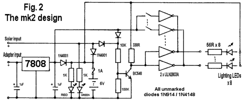
This description applies to the mk2 version. The battery is charged by current arriving from two routes. The first is the 7808 8-Volt regulator which in turn is powered from a wall socket adapter having a 12V DC output. The current passes through one of the 1N4001 blocking diodes which also drops the voltage by around 0.7V bringing it into line with the batteries charging requirements. The other source is the solar panel which again feeds through another 1N4001 blocking diode. This diode is not essential as the panel will withstand the battery voltage across it, even in darkness without harm but it provides a degree of protection should the wires to the panel become shorted.
The emergency lights are driven by a pair of ULN2803A driver ICs. These are nothing more than eight identical power transistors with input current limiting resistors and they could be substituted with discrete components if needed. They can only sink current, not source it, so the lighting LEDs have to be driven from the battery supply with the driver in the ground return path. The ULN2803As are driven in pairs, the sixteen output pins are joined into two groups of eight. One of the pair is enabled by the manual override switch, the other by a power sensor circuit. The override switches are fed from the output of the voltage regulator so they cannot be used if the AC power is lost. Whenever either AC or solar power is present, the transistor is biased on through the 10K resistor. This drops it collector voltage to near zero and turns the other driver off. Only in the absence of both solar and AC power does the transistor turn off, allowing the driver to turn the LEDs on. The two 1K resistors feed monitor LEDs, red to indicate AC is present and green when the solar panel is providing power.
The LEDs I used are high-intensity white ones. You can use conventional incandescent lamps if their current rating is no more than about 200mA. With LEDs, is essential to use a resistor is series with one of its legs, if you connect without a resistor you will get either a blown LED or fuse or most likely both. For 5mm white LEDs use a 82R resistor to give a current of about 25mA. In one location I used a Lumiled device and 10R resistor to set the current at about 150mA. This one LED gives about 15 Lux illumination, far too bright to look at directly and enough output to brightly light a small room. You can run one Lumiled or 5 standard LEDs from each of the driver outputs.
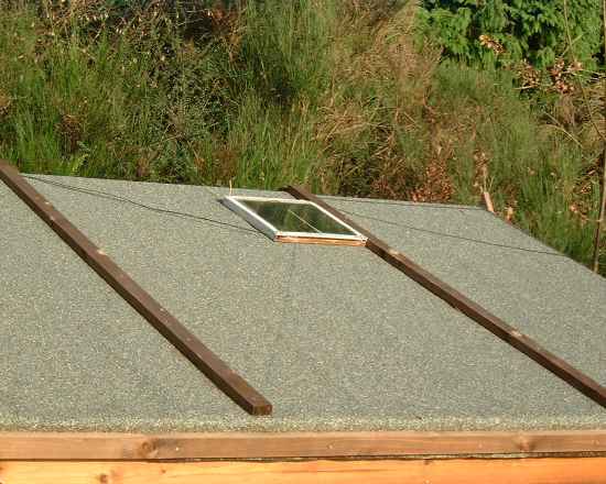
The PV panel I used came from a scrapped water feature, one of those floating fountains that spurt water from a floating plastic island you put in a pond. Fortunately for me, this one sank and was about to be thrown out. It had two small panels in it which despite some corrosion would still deliver 6V each at about 100mA load. I joined to two in series to give 12V total. It isnt necessary to limit the charging current from the PV units, as it cant supply enough to do any damage to the battery. The mains adapter was sourced from Maplin and rated at 12V, 800mA but any output voltage up to about 15V will do. The battery is a sealed 6V 10AH Yuasa model NP10-6. They can be used any way up but I recommend you keep them terminal side topmost just in case of leaks from their vent holes.
If you really need more powerful lighting, I suggest using the LED outputs to drive relays rather than trying to directly drive (sink) more current. Use the relay contacts to control the extra lights. You will, of course, also require a larger battery to store the additional power the extra lights require.