Modifications to the Advanced ATV Repeater to replace the VCR with a Lite-On LVW5006 DVD Recorder.
At first this may seem a like the simple task of removing one unit and dropping the other in its place. However, life is never as simple as that and several modifications have to be made.
The IR command codes are completely different between the original Toshiba VCR and the Lite-On unit but thankfully, both use the same carrier frequency (38KHz) and encoding system. There are also some differences in the command structure that require a different sequence of commands be used. For example, the stop command on the VCR did just that while the DVD goes first into a pre-stop (pause) mode and needs a second stop command to completely end play or record mode. There is also an additional need on the DVD to be able to navigate through the menu to select individual recordings
.
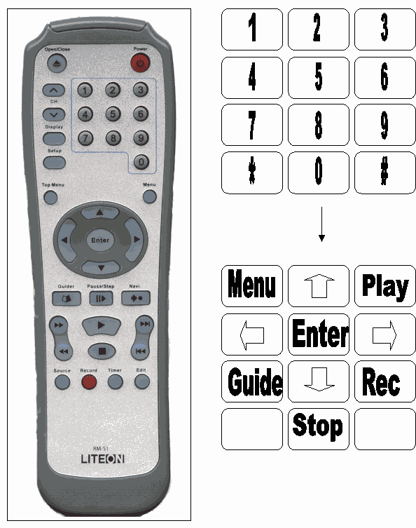
The user keypad, assuming a standard telephone style pad is utilised, has been mapped so it closely follows the functions of the real remote control. The centre 5 key becomes select and the keys left and right of it (4 & 6) become navigate left and navigate right. Similarly, keys 2 and 8 become navigate up and navigate down respectively. The remaining corner keys are used for the stop, play, menu and record controls. The column four tones that are not normally available from a keypad may be used if desired to cycle the mains power, initialise the unit and enter the setup menu. The latter may be needed to periodically correct the time or date and occasionally to format new DVD media. Fig 1 shows the new keypad layout. The changes to the IR commands are achieved by reprogramming the IR-CTRL processor on the SYSPROC board and the changes to the command structure by reprogramming the SAP processor. No component changes are necessary
The second major problem with the conversion concerns the sync detector circuitry. When a VCR is used, in the absence of signal from the receiver, noise is passed through. The sync detector on seeing no recognisable video in the noise will tell the SAP (or external computer) that nobody is using the repeater and a testcard should be broadcast. The DVD recorder however, always produces syncs as in the absence of signal it substitutes it own so that the on-screen graphics and messages can be shown. This fools the sync detector into thinking the repeater is constantly in use.
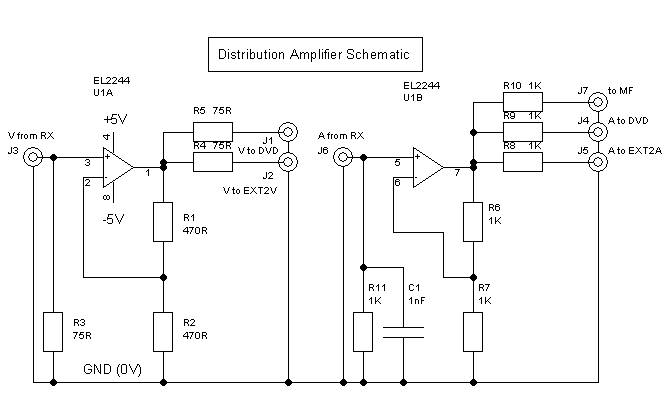
The solution to the sync problem is to route the signal from the receiver to both the repeater RX inputs and the DVD recording inputs. The DVD output going to the EXT2A and EXT2V inputs instead. By moving the DVD out of line of the RX inputs, its internally produced syncs no longer interfere with any signals from the receiver. The drawback to this method is that the receiver is now feeding two loads, the repeater logic and the DVD recording inputs. A distribution amplifier has to be added to maintain the video and audio levels. A bonus to this method is that the MF input which previously had to be connected to the receiver audio output before the VCR, can now also be produced by the distribution amp. The amplifier schematic is shown in fig 2. The amplifier is external to the repeater logic housing. In GB3ZZ, the power for the amplifier was derived form the +12V output on the power supply. This was previously unused and is now connected to a socket on the rear panel via a 1A fuse to save using a separate mains adapter.
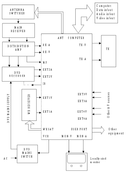
The new connection diagram is shown in fig 3. Comparing this with the one in the original hardware documentation will help explain the changes.