Antenna Switcher Unit for the Advanced ATV Repeater
Originally designed for use with the Repeater unit described in recent CQ-TV magazines, it allows on-site selection or remote control by DTMF tones of one-of-six directional Yagis or an omni-directional Alford Slot antenna.
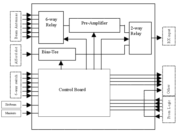
The antenna switcher unit is a mains powered box containing a pre-amplifier, bias tee, antenna selection relays and a control board. On the front panel is a rotary control for selecting one of six directional beams, a toggle switch to control routing of the selected beam or the Alford slot antenna to the receiver and a switch to select manual or automatic control. When manual operation is chosen, control from the main logic unit is disabled and the other front panel controls decide which antennas signal reaches the output socket for connection to the receiver. Under automatic control, the manual switches are disabled and all selections are made by binary number applied to the 9-way D connector on the rear panel. Actual selection of antenna is achieved using either a rotary relay or a bank of single RF relays.
The antenna control socket on the repeater logic unit also carries signals to the weather satellite receiver and in order that they can still be used, they are passed untouched to a second D socket, also on the rear panel. This socket also carries the antenna section signal so that other equipment downstream of this unit can be controlled if desired. When in automatic mode, the antenna output signals are identical to the ones received from the logic unit, when in manual mode they reflect the state of the current antenna selection. Note that as the logic unit is capable of selecting any one of 16 antennas, when in automatic mode, all four control lines are passed through. In manual mode it is only possible to select one of seven antennas (6 plus the Alford slot) which needs three control lines, the most significant bit, bit 3, is therefore always held low in this mode.
Block diagram:
Notes:
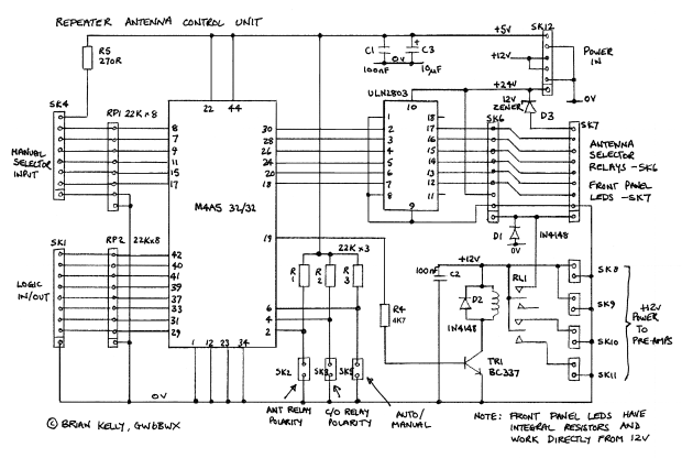
Zener diode D3 is used to drop the incoming 24V down to 12V to keep the front panel LEDs happy. The LEDs used were in a decorative bezel and designed to mount through a panel. They had integral resistors to allow them to run directly off a 12V feed. Ordinary LEDs should have a suitable series resistor connected to either pin to keep their operating current below 10mA. D3 can be changed to drop any voltage up to about 25V or could be replaced by a link if the relay supply is below 12V.
SK2 and SK3 are designed to be left open circuit or have a jumper fitted across them. They reverse the polarity (on/off or vice versa) of the antenna selector relays an the change-over relay respectively.
SK5 goes to a front panel toggle switch. This decides whether the repeater logic or the manual controls are in charge.
One other toggle switch is connected, it is not shown on the schematic diagram. It connects between the common pin of the manual selector switch and pin 8 of SK4. Normally, one of pins 2 to 7 of SK4 will be pulled high by the selector switch, opening the toggle switch lets them all go low, this deselects all the antennas, operates the change-over relay and enables the power feed to the bias tee so the Alford slot pre-amp operates.
Connections:
SK1:
1 - ground
2 - logic input D0
3 - logic input D1
4 - logic input D2
5 - logic input D3
6 - logic output D0
7 - logic output D1
8 - logic output D2
9 - logic output D3
SK2: - link to reverse the state of all antenna selector relays
SK3: - link to reverse the state of the change-over relay and pre-amp power outputs
SK4:
1 - ground
2 - high to manually select antenna 6
3 - high to manually select antenna 5
4 - high to manually select antenna 4
5 - high to manually select antenna 3
6 - high to manually select antenna 2
7 - high to manually select antenna 1
8 - high feed to common pole of selector switch (see notes)
SK5: - to front panel manual/automatic switch
SK6:
1 - switched 12V to change-over relay coil
2 - ground
3 - unswitched 12V to selector relay common connection
4 to 9 - switched ground to low side of selector relay
SK7:
1 - switched 12V to anode (+) of front panel LED (Alford slot in use)
2 - ground
3 to 8 - cathode end of LEDs to indicate antennas 1 - 6 are in use.
9 - common (+) supply to LEDs on pins 3-8
SK8 & SK9: these are switched power feeds to pre-amps if required
SK10 & SK11: these are unswitched (always on) feeds to pre-amps if required
SK12:
1 - power input to selector relays (12 to max 30V)
2 - ground
3 & 4 - +12 for on-board relay and pre-amp power outputs
5 - ground
6 - +5V for PLD.
Click HERE for the PCB and PLD JEDEC files
Provision is made on the controller board to either keep the bias-tee (used to power the Alford Slot pre-amp via its feeder cable) and the internal pre-amplifier powered all the time or to selectively power it up only when in use. For example, it is possible to power down the beam pre-amplifier while the slot antenna is in use and vice-versa. Links are also provided on the PCB to reverse the polarity of the drive signal to both the 2-way chnage-over and 6-way relays. This is to allow the relays to either high side or low side driven depending on the type being used. Drives are made available to operate LED indicators to show which antenna has been selected, these LEDs work in manual and automatic modes. The PLD on the control board is statically operated, it has no clock signals and therefore should not be a source of electrical noise.
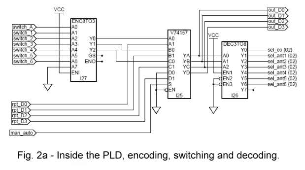
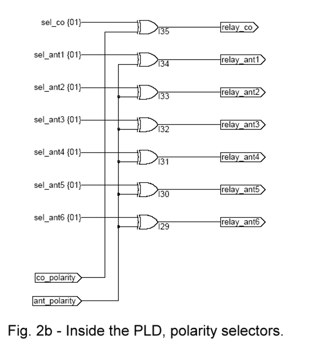
The internal schematic of the PLD is shown in figure 2a and 2b. Basically, all it does is select one of two sets of input lines and routes them to the output pins. However, because one set comes from the mechanical switch where none or only one of the inputs is active at any time and the other input is from the repeater logic which has the antenna number in binary, some converting has to be done. The output is in binary and one of the inputs is binary so it made sense to convert the odd one out to binary as well. Looking at fig2a, the device on the left is a 'one of eight' to binary converter, the middle device is a four-pole two-way switch with its outputs made directly available for other equipment at the back socket. The device on the right does the opposite of the one on the left, it converts the binary lines back to one of eight although only seven outputs are actually used. These are the signals which will ultimately control the relays and LEDs. Note that this selection is either the same as selected by the mechanical switch or the same as selected by the repeater logic, depending on the state of the auto/manual switch. The section of PLD in fig2b serves to reverse the polarity of the relay drive signals to suit different external driver circuits and relay types. Less than half of the PLD is used but in terms of cost and complexity, it is a better solution than discrete devices, especially when you consider that the pins on the chip can be assigned to make the PCB layout easier.
Will the person who complained that these PLDs cost £75, look in the catalogues, they cost under £5!
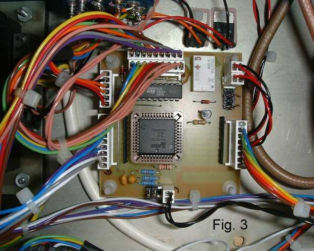
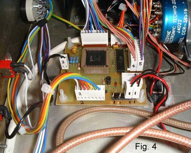
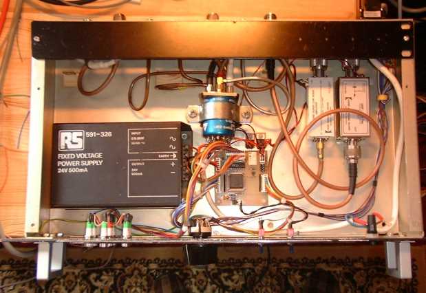
Figures 3 and 4 show the assembled PCB in-situ in the box and figure 5 shows the completed unit from above. The large PSU was used because it was available, it doesn't have to be anywhere near as big as the one used in the prototype. The PCB draws less than 50mA but the total drawn by the whole unit will be more, depending on the relays being used and the current consumption from the bias tee and pre-amplifier. There is no voltage regulation on the PCB but with such little consumption it shouldn't be hard to supply it with a steady 5V. The unit in the photographs used 12V and 5V linear regulators to feed the PCB and these were derived from the 24V used to operate the rotary selector relay.
Note a 'bridge' of tin-plate (as cut from a can of beans!) MUST be fitted between the central copper land under the PLD and the copper border area. Without it the unit will not function and damage may occur to the PLD. To have incorporated it in the PCB layout would have forced a two-layer board which would have made it far more difficult to fabricate at home.